Products

- Product
- Triple/Dual/Single Repeater/Booster
-
2G & 3G 20dBm Dual Booster Specification
- 4G Digital 33dBm Repeater Specification
- 3G Digital 9dBm ICS Home Booster Specification
- 3G & 4G 14dBm Triple Bands Booster Specification
- 3G & 4G 40dBm Triple Bands Repeater Specification
- 3G 7dBm PICO Home Booster Specification
- 3G 7dBm Band Selective Repeater Specification
- 3G 40dBm Repeater Specification
- 2G & 3G 20dBm Dual Booster Specification
- 2G & 3G 36dBm Dual Repeater Specification
- 4G 17dBm Dual Bands Booster Specification
Triple/Dual/Single Repeater/Booster
-
-
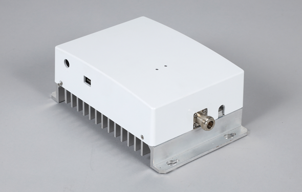
2G & 3G 20dBm Dual Booster Specification
Model No. U-1821S
A. Electrical Specifications 2G
| No. | Parameters | Specifications | |
|---|---|---|---|
| 1 | Frequency Range (1 Band) | UL | 1743.7~1754.9MHz |
| DL | 1838.7~1849.9MHz | ||
| 2 | Frequency Bandwidth | 11±0.2MHz | |
| 3 | Gain | UL | ≥75dB (inband ≧75dB) (Factory setting on 55dB) |
| DL | ≥75dB (inband ≧75dB) (Factory setting on 55dB) | ||
| 4 | Gain Flatness | ≦±1.5dB (inband=75~78dB) | |
| 5 | Manual Gain Control (Step Attenuation) | ≥30dB @ 1dB/Step (UL & DL indivisual) | |
| 6 | Auto Gain Control | ≥30dB (UL & DL indivisual, UL Gain Trailing function) | |
| 7 | UL/DL Band Rejection | ≥105dB | |
| 8 | Output Power | ≥+20dBm/total output power (In-Band≧20dBm) | |
| ≥+17dBm @2 channels(tones) | |||
| 9 | Auto Shutdown Level | ≥+23dBm | |
| 10 | Out of Band Gain | ±400kHz | ≤50dB |
| ±600kHz | ≤40dB | ||
| ±1MHz | ≤35dB | ||
| ±5MHz | ≤25dB | ||
| 11 | 9kHz~1GHz | ≤-36dBm | |
| 1GHz~12.75GHz | ≤-30dBm | ||
| 12 | Spurious Emission | 9kHz~150kHz | ≤-36dBm/1kHz |
| 150kHz~30MHz | ≤-36dBm/10kHz | ||
| 30MHz~1GHz | ≤-36dBm/100kHz | ||
| 1GHz~12.75GHz | ≤-30dBm/1MHz | ||
B. Electrical Specifications 3G
| No. | Parameters | Specifications | ||
|---|---|---|---|---|
| 1 | Frequency Range | UL | 1945~1960MHz | |
| DL | 2135~2150MHz | |||
| 2 | Frequency Bandwidth | 15MHz | ||
| 3 | Channel Raster | 200kHz | ||
| 4 | Gain | UL | ≥75dB (inband ≧75dB) (Factory Setting on 55dB) | |
| DL | ≥75dB (inband ≧75dB) (Factory Setting on 55dB) | |||
| 5 | Gain Flatness | ≦±1.5dB (inband=75~78dB) | ||
| 6 | Manual Gain Control (Step Attenuation) | ≥30dB @ 1dB/Step | ||
| 7 | Auto Gain Control | ≥30dB | ||
| 8 | Gain Trailing Function | When DL AGC be activated, booster gain in both DL and UL path shall be controlled to keep the output level not over Max output level automatically and simultaneously | ||
| 9 | Output Power | UL & DL | ≥+20dBm @total power (inband Min.) | |
| ≥+17dBm @2 FAs(tones) | ||||
| 10 | Auto Shutdown Level | ≥+23dBm | ||
| 11 | Out of Band Gain | 2.7≤f_offset≤3.5MHz | ≤60dB | |
| 3.5≤f_offset≤7.5MHz | ≤45dB | |||
| 7.5≤f_offset≤12.5MHz | ≤45dB | |||
| 12.5MHz≤f_offset | ≤35dB | |||
| 12 | Input inter-modulation | fully comply with 3GPP 25.106 chapter 11 | ||
| 13 | Output inter-modulation | fully comply with 3GPP 25.106 chapter 12 | ||
| 14 | Spurious and intermodulation | fully comply with 3GPP 25.106 chapter 9 | ||
| 15 | Tx/Rx Isolation | ≥90dBc | ||
| 16 | Error Vector Magnitude (EVM) | ≤10% RMS | ||
| 17 | ACRR (Adjacent Channel Rejection Ratio) DL | ≥20dB (5MHz & 10MHz) | ||
| 18 | ACRR (Adjacent Channel Rejection Ratio) UL | ≥20dB (5MHz & 10MHz) | ||
C. Common Specifications
| No. | Parameters | Specifications |
|---|---|---|
| 1 | Noise Figure | ≤6dB |
| 2 | Return Loss | ≤-14dB |
| 3 | Group Delay | ≤6us |
| 4 | RF Connectors | 2 Input(DCS*1, WCDMA*1) 1 Output ports, Type: N-female |
| 5 | Operating Temperature | 0~50℃ |
| 6 | Environment Condition | IP31 |
| 7 | Weight | ≤10kg |
| 8 | Dimension | ≤12 Liter |
| 8 | RCU & Antenna combined loss | ≤15dB (RCU should work when donor antenna locate in -85dBm area) |
| 9 | Remote Control Unit | via USB port at local site / Via 3G wireless modem at remote site |
| 10 | Local Control | via USB port to laptop or PC |
| 11 | Backup battery | AC Fail Alarm sending to OMC Server. The battery life time should be working at least 5 mins when AC fail For Battery ( Charge Capacitor ), PWR LED will blink until fully discharged. |
| 12 | Alarm | Isolation detect Alarm* , AGC out of range, PA output power alarm, DC power failure, Door open alarm(if has door), Temperature alarm |
| 13 | Power Unit | 1. External Type of AC (110~220V, 20%) to DC adapter with INTERNATIONAL SAFETY APPROVAL (CE, GS, CSA, UL, 3C, NSDFI,…) |
| 14 | Reset | On the GUI, system reset will make Modem reset at the same time. |
| 15 | LED Indicator | PWR LED ( Normal Green / Fail Dark ) 2G Alarm LED ( Normal Dark / PA Alarm RED / ISO Alarm RED Blink ) 3G Alarm LED ( Normal Dark / PA Alarm RED / ISO Alarm RED Blink ) |